Mr Sprite Tech
(C) 2012-2013 by Antoine VIGNAU and Olivier ZARDINI
> What
is Mr Sprite Tech ?
This
article is a technical presentation of the sofware Mr Sprite and its inner
algorithm.
We hope that the technical information given here and the available source code will help you in your own projects.
> Apple
IIgs Hardware
CPU
The
Apple IIgs cpu is the 65c816, a 16 bit microprocessor using a 8 bits data bus and a 24 bits address
bus. The good news is that it can address MB of RAM and handle 16 bit
numbers, the bad news is that all it can do is read or write one BYTE after
the other. So writing 16 bits into memory will cost more cycles than
just writing 8.
The 65816 is a low tech microprocessor, just a 16 bit '6502' :
-
only one generic register (A), two index registers (X, Y) plus extra
one-purpose registers (Stack, Status, Direct Page...).
-
no multiplication, division or advanced processing instructions
(Arithmetic Shift for more than one position...)
-
no post-incrementation of the registers
-
no trace mode or administrator mode
-
the 16 bit registers keep the code into 64 KB boundaries ($01/FFFF + 1 = $01/0000). Up to you to
jump from one bank to another one.
- the Stack and the Direct page are 'locked' into bank $00
- a very low frequency (2.8 Mhz for the IIgs, 3.5 Mhz for the Super
Nintendo...)
- an Apple IIgs memory organization that forces a 1 MHz access for any
writes in banks $E0 or $E1 8-[
A few good news :
-
a very compact object code (one BYTE per Opcode)
-
a number of cycles per instruction very low (2 for basic operations, 5
or 6 for memory reads / writes)
- a progressive
cycle cost for
addressing modes (small
for Direct Page or Stack, medium
for current bank and large
for other banks)
Two miracles :
-
The Shadowing lets you work in bank $01 (or others) and what you
do there is mirrored to bank $E1. Not at full speed, but it is still
better than working directly in a low speed bank.
- For
Auxiliary Ram compatibility purpose (I guess ?), the Stack and the
Direct Page my be located anywhere in Bank $01. Amen.
The Apple IIgs is running a 65c816 microprocessor at 2.5
MHz (2.8 MHz from code located in Rom). Per second, we have 2,500,000
cycles. The screen is refreshed 60 times per seconds, so the number of
cycles available per scan is about 41666.
Adding a accelerator card helps a lot, but all the accesses to
$E0 and $E1 are still at 1MHz.
GRAPHICS
Unlike
the processor that was considered 'light' when it was delivered
(yes, Macintosh and other folks were already running 32
bits 68000 at 8
MHz ...), the Apple IIgs graphic capabilities
were cool.
The good:
-
320x200, 16 colors / line, 4096 in the palette / 32 KB size. No trick
or complex memory organisation. We have 4 bits per pixels, 2 pixels /
bytes. All linear, the begining of line N start at the end of Line N-1.
- 16 Palettes, so 256 colors on the screen without CPU usage or complex
palettes switch.
- 1 SCB / line : how to quickly choose palette, resolution, Fill Mode
and Interruption for each line.
- Fill Mode. Never really used in the past decades, but probably plenty
of fun things to do with with it on a rainy day.
- Few softswitchs indicating the line currently refreshed
by the spot. We really need such information to obtain synchronized
animations.
-
All graphic related stuff packed together in memory (graphic page, scb,
palettes) so dumping this memory area gives us a easy to use
graphic file.
-
16 colors in 640 mode. Not real ones but the dithering process gives us
a colorful Finder in 16 colors where Amiga guys had a 4 colors and the
Atari ST folks only 3 !
The
bad :
-
The graphic page address is fixed, in $E1/2000. No possibility to
choose a dynamic address. Good bye hardware scroll...
-
Only ONE graphic page. Impossible to prepare a picture on Page #1 while
Page #2 is displayed and switch to Page #1 when
ready, unlike
we did on the Apple IIe.
The
ugly :
-
The graphic page address is... $E1/2000, yes, in one of the two slow
memory Banks ! Not only we have 32 KB to update with a 8 bit Data bus
microprocessor but they decided to put the graphic page at a location
we can only access at 1 Mhz
8-[
Conclusion
Is
this as bad as it looks ?
No,
hopefully. Of course we don't have all the cpu power we would dream of
(Apple IIe is 1 Mhz for 8KB graphic Page, Apple IIgs is 2.5 Mhz / 32
KB) but the advantage of the IIgs is its simplicity. Everything is easy
to do and designed in the easiest way for the programmer. If you
remember how colors were coded in Apple II's HGR (1 bit to decide the
color
scheme, 1 bit for the pixel to be ON or OFF plus other funny things
like the ODD / EVEN columns and the fact than the graphic page is not
linear) we can say THANK YOU for the Apple IIgs graphic page
organisation. Anyone, after one afternoon of work, can display
something in the Apple IIgs graphic page.
Looking
to other similar computers (Atari ST, Amiga, Macintosh & PC),
the
Apple IIgs is not that far from the top. In 1986, a Macintosh
is
a black & white computer, with no joystick connector and
nothing
done for low level programming. The PC has a CGA / EGA graphic card, no
sound
and so many configurations (CPU frequencies) that we can't really speak
about 'computer' but 'family of'. The closest machines were the Atari
ST and
the Amiga. With the Apple IIgs they were sharing the same vision, a
multi-media computer for home, affordable, and multi-purposes. None of
these computers received any professionnal software (Excel, Word,
Lotus 123...) and all the three
died in the late 90s, due to the move of PC computers
as multi-media
machines (Doom killed the market, showing that the PC was now THE game
machine). Since the Apple IIe reign, for the first time, you have with
a
PC the multi-media and the professional software together on a single
machine. Before
that, the Apple IIgs was a winner for education in the USA.
In Europe the Atari ST was very popular for musicians (due to built-in
Midi connectors) and the Amiga was the best for demos and
homebrew graphics
(DeluxePaint) & musics (Modules). Games were very good of the 3
machines. The European market of the Atari ST & Amiga drives
them
into arcade style games and the USA market drives the Apple IIgs
more into
adventure style games.
For
graphic capabilities, let's say games & animation, the Amiga
comes
first, followed by the Atari ST and so the Apple IIgs. Anyway, all are
close
together, despite Amiga dedicated graphic CPUs (Blitter, Coper). Even
if their 68000 at 7/8 Mhz is much more powerful than our 65c816 at 2.5
Mhz,
their graphic page organisation consumes a lot of power. For the Amiga
(7 Mhz, 40 KB graphic page),
the graphic page is divided into 5 different areas, each coding 1 of
the 5 bit
plan. With 32 colors on the screen, you need 5 bitmap area of 320x200
bit each (8 KB). So, if you want to display 1 pixel using color 1F, you
have to
update in 5 different memory locations, the 5 bits. Because you have a
68000,
you must use the .B (BYTE) adressing mode because the other ones (.W
and .L) don't want to write to ODD address. To summerize, you need 5 read
/ write to memory to switch on 1 pixel. On the Apple IIgs, you need
juste 1
(LDA / [ORA] / STA). On the Atari ST (8 Mhz, 32 KB graphic page), they
did not separate
the bit plan into several areas but they mixed them together with an
interleave of 1 WORD. So once again, if you want to display a pixel
using color F
(Atari ST has 16 colors), you have to update 4 consecutive WORD
(4 read
/ write) : the 4 bits of 1 pixel is coded in 4 consecutive Words. The
65816 doesn't have issues with addressing ODD addresses so no need for a weird
memory organisation to provide EVEN addresses only. The conclusion is
that on Atari ST and Amiga, you spend your time and your energy to
shift sprites bits to display them at the right position (as we did in
the Apple IIe where we needed 7 sprites to cover all possible X
positions). The other things that put the IIgs close to the 2 others is
the 16 palettes / 256 colors mode we have. On the Atari ST or the
Amiga, you have to program a palette switch, using interruptions. This
is more complex and required few extra CPU power. The other advantage
of the
IIgs over the Atari ST and the Amiga is the expansion slots. You can
expect from the Apple IIgs users to have 2 MB or more. The Atari STF is
limited to 1 MB and most sold units were delivered with only 512 KB.
Same
thing with the Amiga 500 where 512 KB was the core market and few had 1
MB. The Atari ST / Amiga market was targeted for 512 KB machines.
Some games were requiring 1 MB, but they were rare. With our 2 MB (or
plus) plus an hard drive, the Apple IIgs can use pre-computed stuff to
lighten cpu
work where the Atari ST & Amiga guys have to compute in real
time
what they want to display.
So
why games are much better on the Atari ST and the Amiga ? At
least 3 reasons. The first one, an probably the more important, has
nothing to do with with technical considerations. Atari ST and Amiga
were strong in the european market and were sold as game machines. So a
lot of small companies entered into the business for creating games for
these two low cost computers (in Europe the IIgs was 3 times more
expensive than the ST or the Amiga). Competition is good for the
quality and everyone was trying to do better than the other companies.
Every new game was superior to the previous one. Because the two
machines had similar hardware (68000 microprocessor, 320x200
resolution,
same joystick, about the same number of colors on the screen), they
were capable of limiting the effort by re-using the same code &
graphics for the two computers (this also explains
why the first Amiga games do not use the real capabilities of
the machine
but are lowered at the ST level). More games = More gamers
buying
an Amiga or a ST computers so more companies entering in the market.
So, if the games were very good on these platforms, it is firstly because
of the number of qualified people trying hard to do so. How many good
game programmers did we have on the IIgs ? Probably less than 10.
So how many games push the IIgs to its limit ? Probably the
same
number ! Have we really seen the limits of the IIgs ? Probably not.
Of course some technical criterias help to
understand the gap between the 3 machines. Atari ST and Amiga can use
any part of their memory as graphic page (the ST must starts its
graphic page on 256 bytes boundaries = no hardware scroll possible).
This means they have as many graphic pages as they want. You can
prepare the picture to display on Page #2 while Page #1 is on the
screen
and immediately display Page #2 by modifying a vector. Impossible to do
that on the IIgs because of the unique Graphic page. If you can switch
from one page to another immediately, you can have smooth full screen scrolling
(even if it is slow), not jerky scroll where you can see
jaggies like we have on the Apple IIgs. The Amiga has a blitter, a
hardware
chip capable to copy memory blocks from one location to another
applying logical operations (AND, OR...) on the fly. You can't imagine
a better help to manipulate Sprites ! Even if the processor frequency
is 10% lower than the Atari ST (7 Mhz for the Amiga, 8 Mhz for the
Atari) and even if the graphic page is bigger on Amiga (40 KB for
320x200 in 32 colors) than on Atari ST (32 KB for 320x200 in 16
colors), the Amige keeps an advantage thanks to all its dedicated
hardware.
With the arrival of FPS (Wolfenstein 3D, Doom...), the fashion was 3D
and texture mapping. For such rendering, the blitter can't help and the
bit-plan organisation of the graphic memory is a nightmare (modifying 1
pixel = 4 or 5 read/writes). If Wolf 3D went to
the Apple IIgs and not to the Atari ST or the Amiga, it is thanks to
our linear 4 bits / pixels memory graphic organisation. It was the only
one capable to handle this properly. Not a revenge, but a nice joke :
the weakest computer was capable to score where the two champions
failed. The legacy of Atari ST and Amiga games library (more than one
thousand) is a very good thing for the Apple IIgs games programmers. We
can pick up there what we need to build the Apple IIgs release of such
games. The Atari ST version is helpful for graphics (320x200 16 colors)
and the Amiga is helpful for sound effects (8 bit like the IIgs). In
the past, many of Apple IIgs games were converted from Atari ST / Amiga
versions (Space Harrier Demo, Morteville Manor Demo, Plotting,
Teenage Queen, The Tinies, LemminGS...).
The
Apple IIgs has not really been pushed to its limit in the time it was
on the market (unlike the two other european folks). We have seen the
light (Rastan, Sword of Sodam, Task Force...) but not really entered the
room. This is why, two decades later, it is still fun to play with the
IIgs to see what it can really do. At the opposite of our modern PCs
which have nearly unlimited CPU Power, Memory size or Disk space, it is
refreshing to go back to program on a 16 bit machine where you can
touch the limit of the machine in everything you try to do.
>
Displaying Sprites
A
sprite is a visual object you want to display on a screen. It can be
of any size and usually we define it by its width & height. We can
draw a frame around it to define its limit (in sprite sheet) or isolate
each sprite in its own picture :
 |
 |
 |
| Orginal
Size (w=36, h=62) |
x4
Magnify |
x10
Magnify details with pixels separation enable (grid) |
Even
if a Sprite is defined by the frame containing all its pixels, the
sprite itself is not a rectangle. Some pixels in the frame define the
Sprites, the other ones are considered as 'background' (in
light blue here).
The
sprite is supposed to be displayed on a picture. The picture with no
sprite is named 'background', as opposite to the sprites supposed to be
displayed in the foreground.
|
+ |
 |
= |
 |
| Sprite |
+ |
Background
Picture |
= |
Foreground
Sprite + Background
Picture |
If
we directly cut / paste the sprite in the picture, we bring also the
sprite background color (light blue), and we probably don't want that !
So we need extra information to define which pixels of the sprite
picture is part of the sprite and which pixels are part of the
background. We could use a color, like we did here, but because the
Apple IIgs as only 16 colors for its screen, sacrifying one color to
define the backgound area would force us to use only 15 colors for the
sprites. We can do other way by defining a Mask, a negative version of
the sprite :
|
 |
| Sprite |
Mask |
Each
black color pixel defines a valid sprite pixel and the white one define
a background pixel. We can now use the Mask to properly insert the
sprite into the background picture :
|
+ |
 |
+ |
|
= |
 |
| Sprite |
+ |
Mask |
+ |
Background
Picture |
= |
Foreground
Sprite + Background
Picture |
When
you create Apple IIgs games, you provide the Sprite sheet and the Mask
sheet together. To simplify Sprite & Mask identification, you
organize them in the same order in both of your pictures. Here is a
Sprite + Mask sheets example comming from LemminGS game :
Sometimes,
you can compute the Mask picture from the Sprite sheet picture (if you
are not using all the 16 colors). You save few KB on the disk because
you only store one picture instead of two. But once in memory, you need
both pictures to be able to display the Sprite as expected.
Because
Apple IIgs use 16 colors / 4 bits per pixels graphic mode in 320x200
(resolution used by 99% of the games), each pixel is coded using a
hexadecimal value from 0 to F. In our example, The Sprite pixels use
values 1 (grey), 2 (light pink) and 3 (black). The background
color MUST
use value 0
(light blue) :
The mask MUST
use 2 values : 0
(black) for the Sprite pixels and F (white) for
the background :
The background can use any 0-F values, we don't really care
about :
If
the pixel values for Sprite background and Mask are imperative, it is
because the way the Masking process works :
-
We use a AND
to force the background pixels values to 0
-
We use a OR
to force the background pixels to the Sprite values
Let's see that :
- First step,
let's apply the Mask on the Background picture using a AND operation :
Intermediate = Background AND Mask
 |
AND |
 |
= |
 |
| Background
Picture |
AND |
Mask |
= |
Intermediate
Picture (Background Picture with 0 values) |
The
logical AND
forces to 0 all pixels of the Background picture matching a 0 value from
Mask (don't change values for pixels matching a F value). The AND
operation 'clears' the background picture in the area where the sprite
will be displayed.
- Second step, we apply the Sprite on
the Intermediate picture using a OR operation
: Result = Intermediate OR
Sprite
|
OR |
 |
= |
 |
| Intermediate
Picture |
OR |
Sprite |
= |
Result
Picture |
The
logical OR changes
all pixels of the Intermediate picture matching a non
0 value from Mask (don't change pixels matching a 0
value). The OR operation draws the sprite into the intermediate picture.
To summarize, we obtain the Result Picture with a
combinaison of 2 logical operations : Result = (Background AND Mask) OR Sprite
Here we don't care about the colors (blue, green, white,
black...). The only mandatory thing is to have 0 and F values for Mask
and 0 for Sprite background. The AND / OR operations work only with
these values.
> Classic
Algorithm
The
classic way to display a sprite on an Apple IIgs screen use the
following Code sequence, for all the pixels of the sprites :
LDA BACKGROUND
AND MASK
ORA SPRITE
STA SCREEN
We
draw usually directly in Bank $01 (faster because of Shadowing) from a
unknown bank (the code displaying the sprite may be located anywhere, so
we use LONG addressing mode) and we work in 16 bits to process 4 pixels
/ operations. We have to use indexed operations because we have to cover
all sprites pixels. If we have Sprites in bank $04 and Mask in Bank
$05, the code looks like :
LDAL $012000,X
ANDL
$050000,X
ORAL
$040000,X
STAL
$012000,X
To
draw 1 line of the Sprite, we have to loop over all pixels of the line,
using sprite width as limit. We start the code by initializing the
screen address where to display the sprite and the Sprite + Mask
address :
Init
LDA ScreenAddress ; Screen
Address ($2000-$9D00) where the sprite must be displayed
STA
SCREEN1+1
STA
SCREEN2+1
LDA SpriteAddress
; Initialiaze Sprite + Mask address
STA MASK+1
LDA SPRITE+1
LDX
SpriteWidth-2 ;
Sprite width in byte - 2 = (Sprite width in pixel / 2) - 2
SCREEN1
LDAL $012000,X
MASK
ANDL $050000,X
SPRITE
ORAL $040000,X
SCREEN2
STAL $012000,X
DEX
DEX
BPL SCREEN1
We
have now to loop over all lines (sprite height) to draw the whole
sprite :
Init
LDA ScreenAddress
; Screen Address
($2000-$9D00) where the sprite must be displayed
STA SCREEN1+1
STA SCREEN2+1
LDA SpriteAddress
; Initialiaze Sprite + Mask address
STA MASK+1
LDA SPRITE+1
CLC
LDY
SpriteHeight-1 ; Sprite height - 1
ONELINE LDX
SpriteWidth-2 ; Sprite width in byte -
2 = (Sprite width in pixel / 2) - 2
SCREEN1
LDAL $012000,X
MASK
ANDL $050000,X
SPRITE
ORAL $040000,X
SCREEN2
STAL $012000,X
DEX
DEX
BPL SCREEN1
LDA SCREEN1+1
; Update address for next
line
ADC #$00A0
STA SCREEN1+1
STA SCREEN2+1
LDA MASK+1
ADC #$00A0
STA MASK+1
STA SPRITE+1
DEY
BPL ONELINE
RTS
The
green Code lines are only executed once. The blue ones are
executed once per Row (sprite height). The Red ones are executed for
each 16 bits (4 pixels) values (sprite heigth * sprite width / 4).
If we choose to not count the green ones, the number of cycles required
to display a sprite on the Apple IIgs screen is :
2
CLC
;
Clear the carry because of
the ADC #$00A0
3
LDY SpriteHeight-1
3
ONELINE LDX SpriteWidth-2
6 SCREEN1
LDAL $012000,X
6
MASK ANDL $050000,X
6
SPRITE ORAL $040000,X
6
SCREEN2 STAL $012000,X
2
DEX
2
DEX
3|2
BPL SCREEN1
; 3 cycles if we
branch, 2 if not
5
LDA
SCREEN1+1
3
ADC
#$00A0
5
STA
SCREEN1+1
5
STA
SCREEN2+1
5
LDA
MASK+1
3
ADC
#$00A0
5
STA
MASK+1
5
STA
SPRITE+1
2
DEY
3|2
BPL ONELINE
; 3 cycles if we branch, 2 if not
The
formula is : #cycles = 5 +
SpriteHeigth*(3+(SpriteWidth/4 * 31) - 1 + 41) - 1
For our Sprite (width=36,
height=62), the result is 19968
cycles. A little bit more because
we need to initialize the address for Sprite, Mask and screen. We have
also to add the RTS at the end of the code.
This generic
routine can be enhanced in many ways. First idea would be to move it
into Bank $01, so the LDAL / STAL could be turned into LDA / STA. We
would gain 2 cycles (one per instruction). The cycle number would drop
to 18852, but a JSL / RTL + PHK / PLB cost few extra cycles.
This
is still about half of the number of cycles available per scan, if you
expect 60 frames / second.
> Mr Sprite's
Algorithm
The weakness of the classic algorithm is linked to its heavy operations (LDA / AND / ORA / STA) for ALL
4 pixels blocks of the sprite. Furthermore, you have to add the post
decrementation operations (DEX DEX) and the loop jump one (BPL). Bigger is the sprite,
more important is the #cycles required to process the sprite. The
important criteria is not the number of data pixels used by the sprite
but the size of the frame around the sprite (sprite width x sprite
heigth). If we count the number of cycles required for a 4 pixels block
(16 bit), we found 6+6+6+6+2+2+3= 31 cycles, so about 31/4 = 7,75 cycles / pixels !
The
purpose of a Sprite Compiler algorithm is to build a sprite
specific code instead of a generic algorithm valid for any kind of sprite.
A Sprite specific code packs together the sprite data (pixel color, width,
height, background pixel) and the code used to display it. We do not have
anymore the code in one location and the sprite data (+ Mask) in another
place, we mix them both together as a code capable to display the
sprite. In a sprite compiled code, there are no loop anymore. We save
automatically the DEX DEX BPL part, so 7 cycles (22,5 % of the
classic algorithm) !
Let's start with our Barbarian sprite. From a human point of view, the sprite is a set of colored pixels . We have chosen the green color to show the background part of the sprite :
Due to the Apple IIgs 16 colors mode, each pixel uses 4 bits, so we pack 2 pixels in a Byte. For the computer point of view, the sprite is a set of bytes :
There are 3 types of bytes :
- The full background ones (2 green background pixels).
- The mixed ones (1 green background pixel + 1 sprite data pixel).
- The full sprite data ones (2 sprite data pixels).
We can remap our sprite picture by providing a new color mode :
- Green for the full background bytes
- Blue for the mixed bytes
- Red for the full sprite data bytes
This first approach helps us to define the work to do :
- There is nothing to do for Green bytes : Let's ignore them.
- We have to provide a full LDA / AND / ORA / STA for the Blue bytes because we have to take care of the background pixels (it is what we were doing in the classic algorithm).
- We have to provide a basic LDA / STA for the Red bytes : No need to take care of the background (no need for a Mask processing using AND / ORA).
Looking to our Barbarian sprite, it is easy to see than green and red
take a huge % of the picture. Very good news ! Because green
= nothing to do = no cycle needed = big save comparing to classic
algorithm. This time, we only spend CPU cycles for sprite data pixels, not
for background pixels. For the Red ones, it is also a very good news because
we replace our LDAL / ANDL / ORAL / STAL by a basic LDA / STAL :
3
LDA #SpriteData ; Sprite 4 pixels data (16 bit)
6
STAL Screen,X
If we can process 2 red bytes together (16 bit), we drop down from 24 cycles (6+6+6+6) to only 3+6=9 (37,5 %) !
If we process the Red byte alone, we have to use 8 bits code :
2
LDA #SpriteData ; Sprite 2 pixels data (8 bit)
5
STAL Screen,X
This
time, we need only 2+5=7 cycles. As expected, it is more interesting to
work with 16 bits code (9/4=2,25 cycles / pixel) than with 8 bit one
(7/2=3,5 cycles / pixels). Everywhere we can, we have to use 16 bit
code to optimize the ratio cycles / pixels (basic algorithm has a bad
7,75 cycles / pixel). We need 2 kinds of fast code :
- A code to put sprite data on the screen
without looking at the background (red area).
- A code to provide AND /
ORA processing between the screen and the sprite data (blue area).
Based on the the 65c816 instructions set, we can use :
- For the red areas : STA / STX / STY / STZ
instructions (Page Direct, Stack or X/Y indexed) or PHA / PHX / PHY /
PHD / PEA / PEI / PER instructions.
- For the blue areas : LDA / AND / ORA / STA
instructions (Page Direct, Stack or X/Y indexed) or TSB / TRB (Direct
Page) instructions.
The idea is of course to get the fastest
instructions possible. Most of games we know (Sword of Sodam, Task
Force...) use the LDA / STA Direct Page instructions. They
are fast (from 3 to 5 cycles for a STA Direct Page) and easy to
use. They both provide a solution for red and blue areas. We choose NOT to use them. We have prefered to use only Stack instructions :
- PHA / PHX / PHY / PHD and PEA for the red areas.
- LDA sr,S / AND / ORA / STA sr,S for the blue areas.
On red areas, the PHA / PHX / PHY and PHD (all 16 bit) use only 4
cycles ! The ratio is 1 cycle / pixel. You can't have a better one. The
PEA instuction is only 5 cycles (for 16 bits), so the ratio is 5/4 =
1,25 cycle / pixel, still VERY good. The PEA instruction has the power
of a LDA / STA because the Operand is the 16 bit value to put on the
Stack. So a PEA $1234 acts like a LDA #$1234 / STA Screen. The LDA /
STA uses at best 3+5=8cycles (16bits, Direct Page).
The other big advantage of the stack related instruction set is the
Post indexing. You push something at the top of the stack and the stack
pointer is automatically updated. You don't have to care about
incrementing an index.
On blue areas, we use the Stack
related LDA $XX,S and the STA $XX,S where XX is a 00 to FF offset.
So we can address any memory location in a range of 256 bytes of
the current Stack address. Looks like a LDA $Address,X where Address
would be the Stack pointer address and X a value between 0 and 255. The
LDA $XX,S instruction use 4 cycle in 8 bit mode and 5 cycles in 16 bit
mode. The same number of cycles than the Direct Page LDA. The STA $XX,S
uses also 4/5 cycles (as the Direct Page STA). The AND / ORA use
constant values (the Sprite Data), so the number of cycle is very low (2 cycles in 8 bit mode, 3 cycles in 16 bit mode).
So we understand easily that we can go VERY FAST
on red areas pushing values on the stack and quite fast on blue areas
where we can use LDA $XX,S / STA $XX,S instructions. The only thing we
have to do is to put the stack pointer (Stack Register) at the right of
the red area and call the PH* instructions (stack goes forward, from
high to low address). Once at the left of the red area, we can use LDA
$XX,S / STA $XX,S to process the remaining blue areas (now located at
the right of the stack pointer, where the $XX,S can be used) :
 | Step 1 : Put the stack pointer at the end of red area (rightmost position) |
| Step 2 : Use a PH* or a PEA instruction to put 16 bit red data on the screen. The stack pointer is automatically moved of 2 bytes to the left (lower address) |
| Step 3 : Use
a PH* or a PEA instruction to put 16 bit red data on the screen. The
stack pointer is automatically moved of 2 bytes to the left (lower
address) |
| Step 4 : Use
a PH* or a PEA instruction to put 16 bit red data on the screen. The
stack pointer is automatically moved of 2 bytes to the left (lower
address) |
| Step 5 : Use
a PH* or a PEA instruction to put 16 bit red data on the screen. The
stack pointer is automatically moved of 2 bytes to the left (lower
address) |
| Step 6 : Use
a PH* or a PEA instruction to put 16 bit red data on the screen. The
stack pointer is automatically moved of 2 bytes to the left (lower
address) |
| Step 7 : Use a 8 bit LDA $0C,S / AND / ORA / STA $0C,S to process the rightmost blue area ($0C=14 bytes far from of the Stack pointer). |
If there is empty parts (background bytes) in the middle of the sprite, we have to move the stack pointer over the gap :
 | Step 1 : Put the stack pointer at the end of the LEFTMOST red area (rightmost position) |
| Step 2 : Use a PH* or a PEA instruction to put 16 bit red data on the screen. The stack pointer is automatically moved of 2 bytes to the left (lower address) |
| Step 3 : Use
a PH* or a PEA instruction to put 16 bit red data on the screen. The
stack pointer is automatically moved of 2 bytes to the left (lower
address) |
| Step 4 : Put the stack pointer at the end of NEXT RIGHT red area (rightmost position) : Stack Pointer = Stack Pointer + $0A |
| Step 5 : Use
a PH* or a PEA instruction to put 16 bit red data on the screen. The
stack pointer is automatically moved of 2 bytes to the left (lower
address) |
| Step 6 : Use
a PH* or a PEA instruction to put 16 bit red data on the screen. The
stack pointer is automatically moved of 2 bytes to the left (lower
address) |
| Step 7 : Use a 8 bit LDA $06,S / AND / ORA / STA $06,S to process the rightmost blue area ($06=6 bytes far from of the Stack pointer). |
Once
the line has been processed, we move the stack pointer to the next line
and we process it. We always move the stack pointer forward (Stack
Pointer = Stack Pointer + delta), never backward. So we only use ADD
instructions in the algorithm, never SBC. SBC by itself is not a problem
but if we alternate ADC (to jump to next line to process) and SBC (to
move stack pointer on a line over the gap), we have everytime to
provide a CLC (before the ADD instruction) and a SEC (before the SBC
instruction). By choosing only one direction (ADD), we can clear the
carry at the beginning of the algorithm (CLC) and never care about the
carry anymore. We save 2 cycles (CLC) for every ADD operations. This
may seems like small win but a good algorithm is full of this kind of
small gain !
The
stack usually works in Bank $00 but, because of
retro-compatibility reason (Language card in the Apple II), it can also
be put in Bank $01 (same thing for the Direct Page). Because the
Graphic Page can also be put in Bank $01 if the Shadowing is enabled,
the winning combination is :
- Enable Shadowing (STZ $C035)
- Disable Interrupts (SEI)
- Put Stack and Direct Page in Bank $01 (LDA $C068 / ORA #$0030 / STA $C068)
- Put Stack Pointer at the Target Screen location (LDA TargetScreen / TCS)
At the end of the code displaying the Sprite, you have to put everything back in order (Stack & Direct Page in Bank $00, enable interrupts, restore stack and Direct Page register...).
To optimize as much as we can our algorithm, we have to use carefully the 65816 instructions and the 8/16 bits mode :
- Whenever it is possible, use 16 bit instead of 8
bit instructions for 2 bytes (or more) blue areas (LDA ,S / AND # / ORA
# / STA ,S).
- Use 8 bit instructions for 1 byte area (red or blue).
- Use the PH*/PEA instructions on large red areas.
- Use LDA # / STA ,S on small (one or two bytes)
read areas (a single LDA # / STA ,S is less expensive than moving
the stack pointer + using the PH* + moving the satck pointer to the
next location).
To visualize the choices of the algorithm, we provide a new colored vision of our sprite, this time with Orange, Yellow and Purple new color codes :
 |  |  |
Orginal Byte Picture (36 x 62 pixels)
18 x 62 = 1116 Bytes
Color Code : Black = 0, Grey = 1, Light Pink = 2 | Red / Blue Byte Picture
R=444 (39%), B=64 (5%), Background=608 (54%)
16 bit Patterns : 2222 (39), 0000 (39), 0022 ( 9) | Red / Orange / Purple / Yellow / Blue Byte Picture
R=328 (29%), O=58 (5%), P=72 (6%), Y=25 (2%), B=25 (2%)
Background=608 (54%) |
Here are the new color codes for Byte picture :
| Color Code | #Cycle / Pixel | Color Code explanation |
 | N / A | 1 Background byte, nothing to do. |
 | (2+4) / 2 = 3 cycles / pixel | 1 Sprite Byte with 2 pixels of Sprite Data. We use a 8 bit LDA #Data, STA $xx,S to update the screen. |
 | (4+2+2+4) / 2 = 6 cycles / pixel |
1 Mixed Sprite / Background Byte (1 pixel of each). We use a 8
bit LDA $xx,S / AND #Mask / ORA #Sprite / STA $xx,S to update the
screen. |
 | (3+5) / 4 = 2 cycles / pixel | 2 Sprite Bytes with 4 pixels of Sprite Data. We use a 16 bit LDA #Data, STA $xx,S to update the screen. There are not enough data to use PH* or PEA here. |
 | (5+3+3+5) / 4 = 4 cycles / pixel | 2 Mixed Sprite / Background Bytes (at least 1 pixel of background among these 4 pixels). We use a 16 bit LDA $xx,S / AND #Mask / ORA #Sprite / STA $xx,S to update the screen. |
 | (4 or 5) / 4= 1 or 1,25 cycle / pixel |
4 Sprite Bytes with 16 pixels of Sprite Data. We can use PHx or
PEA here because the number of bytes to update is large enough to
legitimate the stack pointer update. |
If we look at the ratio #cycles / byte, the Red bytes goes very fast due to the usage of 16 bits PH* / PEA. So come the Orange (16 bit data storage) and the Yellow (8 bit data storage). Without any surprise, as soon as we have to deal with background data, the ratio is bad. The 16 bits (Purple) is nevertheless much better than the 8 bit one (Blue).
If we look to the % of each color bytes in the Barbarian Sprite,
we can see than the group having a good #cycles / pixel ratio is the
more important one (80 %) :
| Color Code | Number of Bytes | % of Total Sprite Data Bytes |
| | 328 | 64,5 % |
| | 58 | 11,4 % |
| | 25 | 4,9 % |
| | 72 | 14,1 % |
| | 25 | 4,9 % |
The
conversion of the Red / Blue Byte graphic into the Red / Orange /
Yellow / Purple / Blue Byte graphic is done by applying few basic rules
:
- Two Blue close together
become a double Purple (2 x 8 bit LDA / AND / ORA / STA = 1 x 16 bit
LDA / AND / ORA / STA)
- One Red surrounded by Green becomes a Yellow (8 bit Sprite data).
- Two Red surrounded by Green or Blue become a
double Orange (not enough Red to use the PHx / PEA).
- A Blue and a Red close together become a double
Purple if the Red can't be used in a better way with another close Red
(to create a Orange or a large Red area)
- A Red area always requires a EVEN number of Red
bytes (PHx and PEA push 16 bits on the stack). The extra one can
be converted into Yellow or combine with a Blue to create a double
Purple.
- A Blue - Red - Red
- Blue will be converted as Purple - Purple - Purple - Purple because
it is a better choice than Blue - Orange - Orange - Blue (what we gain
with the Orange is not enough compared to what we loose with the 2
Blue).
The optimization of the algorithm uses few tricks :
- Because we don't use the Direct Page, we can use the D register, as well as X and Y (all 16 bits) , to store the most used 16 bits Patterns
(4 pixels) of the Sprite. We will use them in the Red areas with a PHD
/ PHX / PHY but also in the Orange areas through a TDC, TXA, TYA
(instead of a LDA #SpriteData).
- If the color code of the sprite pixel is 0, we don't need the ORA in the code sequence LDA / AND / ORA / STA. The AND has already put the 0 value.
- If the color code of the sprite pixel is F, we don't need the AND in the code sequence LDA / AND / ORA / STA. The ORA forces the value to F.
- We use only one CLC at the begining of the code. All the next to come ADC will work fine because the Carry is not used anywhere else.
- Because the LDA / STA $XX,S adressing mode can
cover 256 bytes from the stack pointer current position, we can process
the current line but also the line below (1 line is $A0 long). So if
there is no Red areas, we can process 2 lines before moving the stack
pointer (2 lines below).
-
We gather all 8 bit instructions together to minimize the number of
switchs between 16 bit and 8 bit modes (SEP #$20 / REP #$30).
- We may use a LDA #SpriteData / PHA instead of a
PEA $SpriteData if there are several other PHA with the same Pattern to
insert in the current Red area.
We can see that the pixel color codes may be important to save few cycles by dropping an AND or an ORA in the LDA / AND / ORA / STA sequence : color codes 0 and F
are the ones to choose for the pixels close to the sprite border. For
the Barbarian sprite, the two colors would be Black and Light Pink.
The following animation shows you how the algorithm works to display the Barbarian picture :
- It process the picture from the Top to the Bottom :
- It process
the Orange / Purple / Yellow / Blue bytes for the current line and the
next one (if there are any) using LDA / STA or LDA / AND / ORA / STA.
This is the cleanup step to ensure you only have Red areas on the
current line and the next one.
- It process all Red areas of the
current line (if there are any) using high speed PH* / PEA.
- It moves the
Stack pointer to the next line (at the rightmost position of the first
Red area).
The 2 BYTE graphics are created by Mr Sprite CODE command if you use the -V flag :
MrSprite.exe CODE -V D:\Project\FullSprite.gif 639C42 000000 636363 FFBD9C
The Red / Blue Byte graphic file name suffix is _B_rb and the Red / Orange / Purple / Yellow / Blue Byte graphic file name suffix is _B_ropyb. The width is half of the Sprite width because we use 1 pixel / Byte :
 |  |  |
| FullSprite.gif | FullSprite_B_rb.gif | FullSprite_B_ropyb.gif |
Looking at the ropyb picture tells you immediatelly if the Sprite display will use a lot of cycles. If you see a lot of Red and very few Blue, this is good news. You can have a look to the Sprites available in the Performance section to compare each other. The bigger one is is not always the one requiring the largest number of cycles to be displayed.
The CODE command also provides some statistics about the number of colored Bytes and their %, for both rb and ropyb pictures :
- Sprite BYTE rb : 18x62 Total=1116, Red=444 (39%), Blue=64 (5%), Background=608 (54%).
- Sprite BYTE ropyb : 18x62 Total=1116, Red=328 (29%), Orange=58 (5%),
Purple=72 (6%), Yellow=25 (2%), Blue=25 (2%), Background=608 (54%).
The
final line indicates the width*height of the Sprite, the size of the
object code and the number of cycles required to run the code (=display
the sprite) :
=> 36*62 pixels, 1483 bytes (2232), 2570 cycles (19968).
Is
the sprite object code size (1483 bytes) very big compared to the
memory space required to store the original Sprite picture (18*62
bytes) and its Mask (18*62 bytes) ? This is another good news from this
study. We consume less space by coding a Sprite into 65816
instructions than having the Sprite as a picture in memory (because we
also need the Mask picture, we have to count the size twice). Mr Sprite
computes you both sizes = the size of the object code (1483) and the
size of the Graphic + Mask (2232). With the Barbarian Sprite, we gain
more than 30 % ! Bigger the background area (Green), the more you
save.
We
also provide a comparison between the number of cycles used by the Mr
Sprite coding (2570 cycles) and the number of cycles used by the
classic algorithm (19968 cycles).
In the source code file, we see again the Sprite information (widh*height, object code size, number of cycles) :
Spr_000 CLC ; 36x62, 1483 bytes, 2570 cycles
SEI
; Disable Interrupts
PHD
; Backup Direct Page
TSC ; Backup Stack
STA StackAddress
LDAL $E1C068
; Direct Page and Stack in Bank 01/
ORA #$0030
STAL $E1C068
TYA
; Y = Sprite Target Screen Address (upper
left corner)
TCS
; New Stack address
LDX #$2222 ; Pattern #1 : 78
LDY #$0000 ; Pattern #2 : 78
LDA #$2200 ; Pattern #3 : 19
TCD
*--
We also provide the statistics for the 3 most used Patterns allocated to registers X, Y and D.
> Performance
Let's
test a few Sprites to see how many cycles they need to be displayed.
Remember, we have around 41,500
cycles available per scan if we want 60
pictures / second animation.
We have selected a set of
Sprites from different famous Arcade games, displayed here in a
320x200 screen where you can see their relative sizes :
Each sprite has between 3 and 16 colors. There is a mix of different
sizes. On
a modern high resolution screen, the native 320x200 looks too small so
we have
magnified x2 all pictures for a better view. We provide the original
Sprite but also the complexity analysis graphic provided by Mr Sprite.
 |
 |
 |
 |
 |
 |
 |
 |
Karate
Champ
32x48 pixels
2168
cycles |
Double
Dragon
20x63 pixels
2479
cycles |
Double
Dragon
20x61
pixels
2472
cycles |
Double
Dragon
32x75
pixels
3591
cycles |
Shinobi
32x57
pixels
2593 cycles |
Shinobi
32x64
pixels
3134
cycles |
Golden
Axe
56x65
pixels
3693
cycles |
Golden
Axe
44x73
pixels
3168
cycles |
 |
 |
 |
 |
 |
 |
 |
 |
 |
 |
 |
 |
 |
 |
Street
Fighter 1
56x92 pixels
6045
cycles |
Final
Fight
84x93
pixels
7193
cycles |
Final
Fight
56x93
pixels
6463
cycles |
Street
Fighter II
116x94
pixels
7056
cycles |
Metal
Slug
164x75
pixels
10198
cycles |
Metal
Slug
156x121
pixels
15967
cycles |
 |
 |
 |
 |
 |
 |
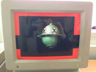
> Proof of
Concept
Here
is an animation of the Metal Slug UFO Sprite using 24 different
pictures (widht=156, height=121) provided as a .2mg image disk (source
code available on disk). The animation runs at 60 frames / second.
Click
to run the animation, click again to quit. The red border shows the CPU
usage (the sprite display is of course faster at 8 Mhz than at 2,5 !) .
We start to draw the Sprite when the spot is refreshing the line
located under the Sprite :
We
can notice than the simulation (KEGS 0.91 running on a PC) does not
provide the same results than the real world ! The real Apple IIgs is
slower than the virtual one. Not a real surprise. If the emulator is
not accurate, it's probably because it does not simulate very well the
Shadowing from $01 to $E1 (1 Mhz speed bank) effect. We write data into
a fast speed bank ($01/2000) but behind, the IIgs have to update the
slow speed bank ($E1/2000) with the same data and this operation
requires extra cycles. All the numbers we have used in this technical
article are purely theoretical. The Shadowing effect has not been taken
into account. What we have tried here, with MrSprite's algorithm, is to
provide the fastest code possible. Fastest in the virtual world is also
the fastest in the real world !
We
will go back into details in this aspect (real cycles / theoretical
cycles) in a next article when we will look at sprites animation,
where the synchronisation with the spot requires all our attention.
MrSprite
Proof of Concept #1